Introduction
Ultrasound detection at the frequency range from kilohertz to hundreds of megahertz is critical for many applications such as photoacoustic sensing and imaging, ultrasonography, navigation, and industrial non-destructive testing [1,2,3]. Commercial ultrasound sensors mainly rely on the piezoelectric effect [4, 5], but their sensitivities drop rapidly as the active area decreases, and the detection bandwidth is generally limited in several megahertz [6, 7]. Over the past years, ultrasound detectors using optical microcavities have attracted considerable interest because of their remarkable sensitivity in micro-nanoscale device sizes [8,9,10,11]. The per-area sensitivity of a silicon microcavity detector could be \(10^8\) times higher than piezoelectric transducers, with an ultrawide detection bandwidth up to 230 MHz [12, 13]. The microcavity ultrasound detectors have been exploited in in vivo photoacoustic imaging and enable great improvements in the imaging contrast ratio and resolution compared with conventional piezoelectric transducers [14,15,16].
Microcavity-based acoustic detectors rely typically on the dispersive mechanism in passive resonators [11,12,13, 17, 18]. Acoustic waves modulate the refractive index and cavity boundary through the photoelastic effect and sound-induced strains [19, 20], leading to the resonance shifts. The rapid acoustic modulation is then translated into the intensity variations of a fixed-wavelength probe light that transmits out of the microcavity-waveguide-coupled system. Since the detection sensitivity is proportional to the quality factor (Q) of the cavity mode, one of the tendencies in recent studies is to develop high-Q microresonators for applications in acoustic sensing and imaging [11,12,13]. In particular, the nonlinear optical effects, such as optothermal effect [21,22,23] and stimulated Raman scattering [24,25,26,27,28], will become significant since the combination of high Q and small mode volume can resonantly build very high intracavity intensities even with small input powers [29, 30]. However, these distinct nonlinear effects in microcavity-based ultrasound sensors are generally neglected previously.
Here, we propose the thermal-assisted Raman laser in high-Q microresonators for ultrasound detection. Experimentally, the noise equivalent pressure (NEP) reaches as low as 8.1 Pa at 120 kHz. Moreover, the acoustic response of the microcavity Raman laser assisted by the thermal effect is analyzed. It is found that the thermal effect can compensate for the low-frequency noises, while without degrading their sensitivity to high-frequency acoustic waves above hundreds of kilohertz. Furthermore, this thermal effect is experimentally harnessed to stabilize the measurements, enabling resistance to the frequency and power fluctuations induced by external disturbances and the laser sources.
Results
Basic characterization of Raman laser for ultrasound detection
Figure 1a shows the schematic of the experimental setup. A 30-µm-diameter silica microspherical resonator with a Q factor above \(10^7\) is coupled to a microfiber for real-time optical readout. A 1480-nm-band tunable pump laser is injected into the microcavity to generate the Raman laser. The transmitted light is divided into three ports to monitor its optical spectrum, the pump power, and the generated Raman power. Here, the pump and Raman light are separated by a band-pass filter (center wavelength: 1480 nm, bandwidth: 12 nm) and a long-pass filter (> 1500 nm), respectively. The principle of ultrasound detection is presented in Fig. 1b. Acoustic waves can modulate the refractive index and cavity boundary through the photoelastic effect and sound-induced strains [19, 20], introducing the frequency shift of the pump mode. The resonance shift then changes the coupled pump power from a fixed-wavelength input laser into the cavity and therefore the output Raman power [26, 28].
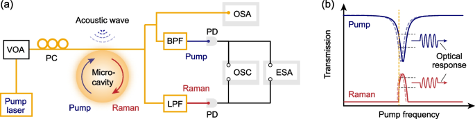
a Schematic of the experimental setup. The Raman laser is generated inside the microcavity, and the ultrasound-modulated intensity variations in the pump laser and Raman laser are monitored in the transmitted light of the microcavity-microfiber-coupled system. VOA, variable optical attenuator; PC, polarization controller; PD, photodetector; BPF, band-pass filter; LPF, long-pass filter; OSC, oscilloscope; OSA, optical spectrum analyzer; ESA, electrical spectrum analyzer. b The principle of ultrasound detection. Acoustic waves modulate the resonant frequency of cavity resonances, altering the coupled efficiency of a fixed-wavelength input pump laser, and therefore the generated Raman power. Blue curve, transmission spectrum of the pump mode. Red curve, the generated Raman power at the different pump frequencies
Experimentally, a blue-detuned pump laser with the power of about 100 µW is injected into the microcavity. As the pump frequency is tuned toward the cavity resonance, the intracavity pump power gradually increases. Once the intracavity pump power reaches the threshold, the Raman laser is stimulated, as shown in Fig. 2a. Here, the pump transmission is broadened due to the light-absorption-induced thermal effect [21,22,23]. The pump transmission measured at a low input power shows a standard Lorentz line shape with the loaded Q factor of \(1.5\times 10^7\) (the inset of Fig. 2a). Figure 2b presents the optical spectrum of the pump laser and generated Raman laser, and the first-order Raman laser is observed as a single line at 1600 nm.
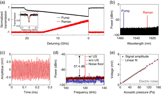
a Transmitted power of the pump and Raman light measured during the pump frequency scanning. The mode lineshape is broadened due to the thermal effect. Inset, the transmission of the pump mode at a low input pump power. b Optical spectrum of the pump and Raman lasers. c Power oscillations of the Raman laser induced by continuous ultrasound wave (120 kHz). d Power spectral density of the Raman laser measured with (red curve) and without (gray curve) the ultrasound wave. Background noise floor measured without the pump light (blue curve). US, ultrasound. e Measured acoustic responses as a function of acoustic pressures. Red line, the linear fit of experimental results (black pentagrams)
The microcavity Raman laser is then exploited for ultrasound detection. A piezoceramic stack is used to generate the continuous acoustic wave with a frequency of 120 kHz in air, and its acoustic pressure of 80.1 Pa is calibrated by a hydrophone [18]. The acoustic response of the Raman laser is measured at a fixed pump frequency and extracted by a band-pass electronic filter in a range of 30–800 kHz. Figure 2c presents the ultrasound-induced power oscillations of the Raman laser, which reveals that the NEP of this sensor reaches 8.1 Pa according to the root-mean-square noise without applied acoustic waves. Besides, the power spectrum density of the acoustic response is measured simultaneously by an electrical spectrum (Fig. 2d). A signal-to-noise (SNR) of 57.4 dB is observed over an integration time of \(\tau = \Delta f^{-1}\), where \(\Delta f=10\) Hz is the resolution bandwidth of the spectrum analyzer. Therefore, the NEP spectral density \(P_{\text {min}}(\omega )=\) 34.1 \(\text {mPa}/\sqrt{\text {Hz}}\) limited mainly by the shot noises is obtained by \(P_{\text {min}}(\omega _{\text {a}})=\sqrt{\tau /\text {SNR}}\times {P(\omega _{\text {a}})}\) [8, 10]. Furthermore, we measure the acoustic waves with different applied pressures, and the responses are demonstrated to be linear with the acoustic pressures (Fig. 2e). Note that the NEP can be improved further by using cavity material with a smaller Young’s modulus and larger photoelastic coefficient.
Thermal-assisted ultrasound detection of the Raman laser
High-Q optical microresonators can resonantly build high intracavity intensities even with very small input power, thereby the distinct thermal effect generally exists with the Raman laser. Typically, as the intracavity temperature increases, both the cavity size and the refractive index change through the thermal expansion and thermal-optic effects, respectively [23]. These thermal effects can shift cavity resonances and therefore may change the optical response of the microresonators to ultrasound modulation.
To study the influences of thermal effects on ultrasound responses, the coupled-mode equations are used to analyze the dynamic evolution of pump and Raman fields inside the microresonator as [25, 31]
where \(a_{\text {p}}\) and \(a_{\text {r}}\) are the amplitudes of the pump and Raman modes, with resonant frequencies \(\omega _{\text {p}}\) and \(\omega _{\text {r}}\); \(a_{\text {in}}\) represents the input pump light with the cavity detuning \(\Delta\); \(\kappa _{\text {in}}\) and \(\kappa\) are external coupling loss and total loss of the pump mode; \(G_{\text {r}}\) and \(\kappa _{\text {r}}\) denote the Raman intracavity gain coefficient and the total loss of the Raman mode. The resonance shift induced by the thermal effect is determined by temperature change \(\delta T\) and thermal nonlinear coefficient \(\gamma _{\text {th}}\). The modulated resonant frequency by ultrasound waves is described by \(\delta _{\text {u}}=A\mathrm {cos}(2\pi f_{u}t)\) with the amplitude A and ultrasound frequency \(f_{\text {u}}\). The transmitted power of the pump light can be derived by \(|a_{\text {pout}} |^2=|a_{\text {in}}-\sqrt{\kappa _{\text {in}}}a_{\text {p}}|^2\), and the output power of the Raman laser can be obtained by \(|a_{\text {rout}} |^2=|a_{\text {r}}|^2\kappa _{\text {r}}/2\).
The temperature change inside the microresonator can be derived by the thermal evolution equation as [21, 22]
where \(\tau _{\text {th}}\) is the thermal relaxation time, \(\tau _0\) is the round-trip time of the intracavity photons, \(\eta\) is related to the efficiency of light absorption, Q and \(Q_{\text {abs}}\) are total and material-absorption-limited Q factors. Here, the temperature changes generally result from three aspects. First, the heat dissipated into the surrounding environment with a thermal conductivity \(1/\tau _{\text {th}}\). Second, the absorbed photons of the intracavity pump and Raman light are converted to heat with the proportion of \(Q/Q_{\text {abs}}\). Third, the energy loss of the inelastic scattering from pump photons to Raman photons also contributes to the heat [32, 33].
Figure 3a and b present the transmitted power of the pump light and the generated Raman light of the microcavity-microfiber-coupled system, respectively. Here, the pump transmission is given without Raman gain (\(G_\text {r}=0\)) to describe the behaviors of a passive microcavity conventionally utilized for ultrasound detection. The pump transmission is broadened due to the thermal effect compared with the cold cavity, and therefore, the generated Raman power satisfies the same tendency as observed in Fig. 2a. The ultrasound responses of the passive microresonator and the microcavity Raman laser are analyzed in Fig. 3c and d. It reveals that for cold-cavity modes, the acoustic responses linearly depend on the slope of the mode lineshape at different pump frequencies and therefore manifest the symmetric doublets along the resonant frequency [8, 10].
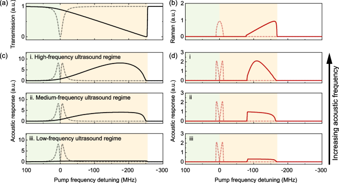
a Theoretical transmission of the conventional passive microresonator (without Raman gain) at different frequency detunings relative to the cold-cavity resonance. In a–d: dashed curves, cold cavity; solid curves, thermal cavity. Green (yellow) shade indicates the red-detuned region of the cold (thermal)-cavity mode. b Theoretical generated Raman power at different pump frequency detunings relative to the cold-cavity resonance. c, d Acoustic responses of the passive microresonator (c) and Raman microcavity laser (d). The oscillation amplitudes are given for three representative acoustic frequency ranges: (i) high-frequency ultrasound regime with \(f_{\text {u}}\gg 1/\tau _{\text {th}}\), (ii) medium-frequency ultrasound regime with \(f_{\text {u}}\sim 1/\tau _{\text {th}}\), and (iii) low-frequency ultrasound regime with \(f_{\text {u}}\ll 1/\tau _{\text {th}}\). Here, \(\tau _\text{th}\) is the thermal relaxation time of cavity material
In the presence of the thermal effect, the acoustic response exhibits different behaviors, which depend on the relative rates between ultrasound modulation (\(f_\text {u}\)) and thermal relaxation (\(1/\tau _\text {th}\), it is about 50 kHz for silica materials). At the high-frequency ultrasound regime with \(f_\text {u}\gg 1/\tau _\text {th}\), the thermal relaxation rate is too slow to affect acoustic modulation (Fig. 3c, d (i)). Therefore, the maximum acoustic response remains unchanged as the cold cavity, of which the acoustic response is only limited by the intracavity photon lifetime [34, 35]. At the medium-frequency ultrasound regime with \(f_\text {u}\sim 1/\tau _\text {th}\), since the resonance shift induced by the cavity temperature variation presents antiphase change with the acoustic modulation, the maximum acoustic response decreases (Fig. 3c, d (ii)). At the low-frequency ultrasound regime with \(f_\text {u}\ll 1/\tau _\text {th}\), the acoustic modulation is so slow that the thermal effect can significantly compensate for its disturbances (Fig. 3c, d (iii)).
The thermal behaviors of the Raman microcavity laser in ultrasound detection are also studied experimentally. The optical responses of the transmitted pump and Raman power to the 120-kHz acoustic wave are monitored simultaneously, as the pump frequency is fixed at certain cavity detunings (Fig. 4a, b). The acoustic responses are observed to remain nearly unchanged when the pump frequency varies at a wide range (about 15 GHz for a pump power about 100 µW), as expected theoretically in Fig. 3d (ii). Note that the slope of the triangular lineshape of the pump transmission suddenly changes once the Raman laser is stimulated, and the corresponding acoustic response shows a step increase by about 7 dB (Fig. 4a). This thermal-assisted performance of this ultrasound detector enables natural resistance to the frequency drifts of the laser sources and that induced by external disturbances [21, 23]. It is demonstrated experimentally by measuring the temporal stability of the detected acoustic responses of both pump and Raman lasers (Fig. 4c). Their power spectral densities at 120 kHz are recorded continuously for 30 min with a time interval of 30 s. The detected acoustic responses remain stable with similar standard derivations for pump and Raman lasers.
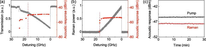
a Pump transmission (gray curve) and corresponding acoustic responses (red circles) at different pump frequencies. In a and b, the cavity detuning at which the intracavity pump power reaches the Raman threshold is indicated by the red dashed line. b Raman power (gray curve) and corresponding acoustic responses (red circles) at different pump frequencies. c Temporal stability of the acoustic responses of both pump (black circles) and Raman lasers (red circles)
Conclusion
In summary, a highly sensitive microcavity-based Raman laser is proposed for ultrasound detection. The NEP is achieved as low as 8.1 Pa at 120 kHz, and the corresponding NEP spectral density reaches 34.1 \(\text {mPa}/\sqrt{\text {Hz}}\). Besides, the sensing performances of the microcavity Raman laser and conventional passive microresonator are studied in the presence of the thermal effect. It reveals that their sensing performances to high-frequency acoustic waves remain nearly unchanged as the cold cavity, with significantly suppressed responses to the low-frequency acoustic waves. This feature is particularly useful to compensate for low-frequency noises from laser sources and that induced by external disturbances in high-frequency acoustic measurements [36]. Our work offers a new perspective to study the acousto-optic interactions in optical microcavities with nonlinear effects, holding great potential in widespread applications ranging from ultrasound sensing and imaging to sonar, navigation, and trace gas sensing.