1 Introduction
The use of machines has been a critical driving force of human civilization since ancient times. With the development of nanotechnology, the nanoscale miniature of machines has drawn more and more interest from researchers of multiple disciplines. Like its macroscopic counterpart, a molecular machine can be defined as an assembly of a discrete number of molecular components designed to perform mechanical-like movements as a consequence of appropriate external stimulation [1]. Notably, a molecular rotor that is capable of full-cycle unidirectional rotations under external stimuli is classified as a molecular motor. Natural molecular rotors such as the F-type ATP synthase [2] play an essential role in biological systems. Artificial molecular rotors are identified to be crucial components of integrated molecular machines. The last three decades have witnessed extensive study of building and controlling molecular rotors and motors with various approaches [3]. For example, the Feringa group has developed three generations of light-driven unidirectional rotating molecular motors [4,5,6,7,8]. However, due to the abundant solution phase analytical tools available to the chemists, most of the abovementioned artificial molecule machines are developed and operated in the solution phase, which limits the possibility of building devices with molecular rotors and makes it impossible to operate an individual rotor. In reality, known natural molecule machines primarily work on the interface. For instance, ATPase is anchored in a membrane [2, 9, 10] and kinesin [11] and myosin [12] walk alone filaments. Inspired by their counterpart in natural biological systems, artificially made molecular rotors and molecular machines that are anchored on surfaces have gained increasing interest.
A scanning tunneling microscope (STM) works on the tunneling current between its atomically sharp tip and the conducting surface. An STM, with functions of imaging, spectroscopy, and atom manipulation, has been proven to be capable of investigating the dynamics of atoms and molecules on surfaces [13,14,15,16,17,18,19]. At as early as 2002, Eigler group had demonstrated that by using the STM tip to arrange CO molecules into specific configurations, one-time molecular cascades can be triggered to perform simple logic operations [20]. Thus, STM is the desirable instrument for observing, validating, and manipulating the rotational behaviors of molecular rotors anchored on the surface.
Here, we review some representative works using STM to experimentally investigate the molecular rotors anchored on surfaces and related surface dynamics phenomena. These works provide a set of methodologies which will be increasingly adopted in future studies of surface-mounted molecular rotors.
2 Scanning tunneling microscope used in imaging molecular rotations
In 2008, the Gao group, renowned for their pioneering work utilizing STM, reported that they had constructed an array of single-molecule rotors [21]. They deposited tetra-tert-butyl zinc phthalocyanine ((t-Bu)4-ZnPc) molecules on the reconstructed Au(111) surface, and they found large-scale ordered arrays of the molecules rotating along the well-defined axis. This work clearly demonstrates the ability of the STM to characterize the topographic properties of the rotating molecular rotors.
A clean Au(111) surface features a (22 × √3) surface reconstruction [22]. The STM image in Fig. 1 (color online) (a) reveals that the molecules are predominantly adsorbed on the elbow positions of the reconstructed Au(111) surface, forming a well-ordered self-assembled molecule array. The circular images suggest a rotation behavior under the STM tip. The high-resolution image in Fig. 1 (color online) shows that the rotation molecules have a “folding-fan” feature, instead of being regular circles under the tip. Notably, the “folding-fan” discovered at 78 K cannot be observed at 5 K. It is thus proposed that the folding-fan feature is a low-frequency sampled image of a high-frequency molecular rotation driven by thermal energy.

(Color online). a STM image of (t-Bu)4-ZnPc molecular rotors on the reconstructed Au(111) surface. A large-scale ordered array is found. b The detailed STM image of single molecular rotors, which features a “folding-fan” shape. The molecular rotors at two different elbow sites “open up” in different direction as a result of the modulation caused by the corrugation ridges. Reprinted with permission from ref. [21]. Copyright 2008 American Physical Society
The rotation centers in Fig. 1 (color online) (a) STM image of (t-Bu)4-ZnPc molecular rotors on the reconstructed Au(111) surface. A large-scale ordered array is found. (b) It is the detailed STM image of single molecular rotors, which features a “folding-fan” shape. The molecular rotors at two different elbow sites “open up” in different directions because of the modulation caused by the corrugation ridges are found to be dark, indicating that the centers cannot be tert-butyl groups, which appear brightly under the STM tip because of their relative height. They proposed that the most likely rotation center is the gold atom. In order to verify this hypothesis, conformation in Fig. 2 is tested by ab initio calculations. First-principle calculations using the Vienna ab initio simulation package (VASP) confirmed that some Au adatoms formed in the sample cleaning process are chemically bonded to one nitrogen atom in the (t-Bu)4-ZnPc molecules, which serve as the rotation centers. The fact that a rotation center is not located beneath the geometrical center of the (t-Bu)4-ZnPc explains the unsymmetrical “folding-fan” rotation.

(Color online). Optimized conformation of a single (t-Bu)4-ZnPc molecule adsorbed on Au(111) surface via a gold adatom (in red). a Top and b side view. Reprinted with permission from ref. [21]. Copyright 2008 American Physical Society
3 Time-dependent tunneling current used in quantitively studying the energy barrier
By putting the STM tip above a certain location of a surface and cutting off the feedback loop, one can obtain the I-T curve of the tunneling current fluctuation against time. This time-dependent tunneling current gives information on the frequency, residue time, and energy barrier of the surface dynamics process that occurs below the tip. This method was first widely used in the investigations of surface diffusion [23,24,25].
Surface diffusion, which is also named thermal hopping when it is driven by thermal energy, is a concept concerning the locomotion of the adsorbed atoms or molecules on solid material surface. The adsorbed particles occupy specific sites, such as bridge sites or threefold hollows among several substrate atoms which are near to each other. Due to the electronic property which has translational symmetry, there exists a potential energy hypersurface representing the adsorbate substrate interaction, and the adsorption sites are the positions of lowest potential energy for adsorption which is repetitive in real space. An STM is capable of studying the topographic properties of the surface diffusion system at an atomic resolution as well as quantitively understating the energy barrier. Wang et al. introduced this methodology in detail in 2005 by studying the single Cu atom diffusion within the faulted half unit cell of \(\mathrm{Si}\left(111\right)-(7\times 7)\) [23]. This technique is also adopted in the research of surface-mounted molecular rotors.
Figure 3 (color online) gives two kinds of nonequivalent adsorption sites of Cu on Si(111)-(7 × 7) surface: the center and corner sites. The hopping rate and energy barrier out of the corner or the center Si-adatom sites can be quantitively studied based on the method proposed by Wang et al. When the STM tip is positioned on one of the center or corner sites, the diffusing Cu atoms confined in the faulted half unit cell of Si(111)-(7 × 7) would repeatedly pass through the site and thus be detected by the tip. This information of thermal hopping is encoded into the time-dependent tunneling current I-T. Assuming that at time \(t=0\) the diffusing particle is at a given site, the probability for it to remain at this site at time t is given by the following:
where \(\Gamma\) is the hopping rate out of this adsorption site. The hopping events are collected in a large scale by recording many I-T curves at a given temperature, as shown in Fig. 4a which is an example of the data procession for the I-T obtained at 208 K. All the hopping events recorded at the temperature are regarded as a statistical ensemble. Figure 4b plots the number of resident events that have a residence time longer than a given duration as a function of time. Equation (1) tells that the inverse of the decay time constant from these plots is exactly the hopping rate out of a given site.

(Color online). STM images of a Au, b Ag, and c Cu atoms on Si(111)-(7 × 7) at room temperature. The high-frequency diffusion of single metallic atoms in a faulted half unit cell causes the bright triangular patterns. The circles and crosses in c indicates the corner and the center Si-adatom sites respectively. d The STM image of the same area of c after cooling to 77 K. The triangular patterns are reduced into single bright spots. Reprinted with permission from ref [23]. Copyright 2005 American Physical Society

(Color online). An example of the data procession for the I-T obtained at 208K. a Time-dependent tunneling current spectra taken above a center and a corner Si-adatom site, respectively. A high plateau indicates the residence of a Cu atom at the given site. It appears that the corner site has a longer Cu residue time than the center site. b The bar distribution of the events with their resident time longer than the given time in the horizontal axis. The solids lines are exponential fits. Reprinted with permission from ref [23]. Copyright 2005 American Physical Society
The hopping rate at different temperatures can be obtained by repeating the experiment varying the temperature of the sample in the STM chamber. These hopping rate data obtained from fitting Eq. (1) at different temperatures are again fitted by the following:
where \({\Gamma }_{0}\) is the attempt frequency and \({P}_{E>{E}_{a}}\) is the possibility that an atom is in a state with higher energy than the energy barrier, which is itself determined by the temperature according to the Boltzmann distribution. k is the Boltzmann constant, and \({E}_{a}\) is the energy barrier for hopping out and into the given site. Taking the logarithm of it, we have another equation:
Figure 5 gives the Arrhenius plot for both the corner and the center sites. The diffusion energy barriers for the center and corner sites are deduced to be the following: \({E}_{a}=0.36\pm 0.02\) eV and \({E}_{a}=0.40\pm 0.02\) eV, respectively.

(Color online). Arrhenius plot of the hopping rate, \(\Gamma\). The circles are data for the center Si-adatom site, and the squares are data for the corner Si-adatom site. Reprinted with permission from ref. [23]. Copyright 2005 American Physical Society
When a molecular rotor anchored on the surface is rotating not in a homogeneous manner but with several residual sites where it stays for a longer time, this time-dependent tunneling current method can also be adopted to quantitively study the rotation frequency as well as the energy barrier for the rotation.
The Sykes group reported their work in 2008 [26] in which they systematically studied a rotor system of a series of thioether molecules of varying lengths that bind to the Au(111) surface through a S–Au bond as the axle and the alkyl tails as the rotator that interacts weakly with the surface. Figure 6 is a scheme of this system. Dimethyl sulfide has a rotation arm with one carbon, ethyl sulfide with two carbons, and butyl sulfide with four carbons.

Dimethyl, ethyl, and butyl sulfide on Au(111) surface. Reprinted with permission from ref. [26]. Copyright 2008 American Chemical Society
A rotor with a longer rotation arm has a greater moment inertia. Figure 7a reveals the effect of temperature on this set of rotors, from dimethyl sulfide to dihexyl sulfide. At 7 K, dimethyl sulfide is imaged as a hexagon, indicating it is rotating, while all the other molecules display as a linear image under STM, which indicates that these molecules are static on the Au(111) surface. The six bright lobes in the hexagon STM image correspond to six positions on the Au(111) surface where the molecule has longer time to stay during rotation. Higher temperatures give higher thermal energy. Thus, from 7 K above, dimethyl sulfide always rotates. The other three molecules are found to have similar temperatures to trigger the rotation at about 15 K. This reveals that dimethyl sulfide has a particularly low-energy barrier for rotation. At the same time, the other three molecules have similar rotation energy barriers. This suggests that the most significant contributor to the rotation energy barrier is the interaction of the second carbon of the alkyl chain with the Au(111) surface.

(Colored online). a STM images reveal the trigger temperature for four molecules to rotate. b Time-dependent I–V curve is used to investigate the rotation speed of dibutyl sulfide. The I–V curves reveal three levels of tunneling current that correspond to the three inequivalent orientations of dibutyl sulfide (blue, yellow, and red) with respect to the STM tip position (black dot). Reprinted with permission from ref. [26]. Copyright 2008 American Chemical Society
They took a time-dependent spectroscopy method to quantitively study the rotation of the rotors, taking examples of the dibutyl sulfide. By doing this, the STM tip is positioned above an asymmetrical point of the molecule. In this case, there are three inequivalent positions for the molecule to stay, and each of them gives a distinct tunneling current. By recording the tunneling current against time, three plateaus corresponding to three staying sites were discovered. This is illustrated in Fig. 7b.
By repeating the experiment at various temperatures, the rotation frequency at different temperatures is calculated based on the time-dependent I–V curves. They are fitted in the Arrhenius plot in Fig. 8. Referring to equation 3, the energy barrier for rotation is calculated to be 1.2 kJ/mol and the attempt frequency to be \(7\times {10}^{7}Hz\).

Arrhenius plot for the rotation of an individual dibutyl sulfide molecule on the Au(111) surface. Reprinted with permission from ref. [26]. Copyright 2008 American Chemical Society
4 Manipulating surface rotation with STM
STM tip applies electric field, as well as tunneling electrons to the rotors on surface, which may be used to manipulate the rotation behavior.
In order to change the rotation status of the rotor while imaging the rotor at the same time, it is desirable to move the rotation axis from vertical to horizontal. In that case, a translation motion is performed by the rotor on surface. A molecule/molecular system which consists of molecular rotors and performs translational movement under STM stimuli is termed as a nanocar. The ambition of building nanocars can be traced back to 1959 when Richard P. Feynman made his historical address “There is Plenty of Room at the Bottom” [27] in which he proposed the concept of constructing a machine in a molecular scale by giving some scenarios, for example, an infinitesimal automobile and the challenges to realize it.
The first nanocar was created in 2005 by the Tour group [28]. They synthesized a kind of molecule at a scale of approximately 3 × 4 nm. The molecule, as seen in Fig. 9, consists of an organic “chassis” part and four fullerene “wheels” attached to it with C≡C triple bonds. The C≡C triple bonds in this nanocar let the “wheels” rotate freely in the experiment.
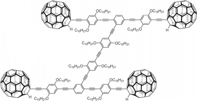
The first nanocar is a single molecule with four free-rotating fullerene “wheels” fragments. The “wheels” and “chassis” are connected by C≡C triple bonds, which give the “wheels” a degree of freedom for rotation. Reprinted with permission from ref. [28]. Copyright 2005 American Chemical Society
The nanocar molecule was deposited onto the Au(111) surface. Figure 10 shows detailed STM images of the first nanocar at different stages of manipulation. The molecule under the STM imaging displays as a four-shining-dots set. Those shining dots are concluded to be fullerenes due to their comparable height. Because the molecule is rectangular but not square, one may determine the orientation of a nanocar. While manipulating the nanocar, the STM tip was lowered in front of the nanocar, and a higher bias voltage pulse was applied to “drag” the nanocar. The “drag” in Fig. 10a successfully moved the nanocar to the position in Fig. 10b. However, when doing the same “drag” on the side of the nanocar in in Fig. 10b, it failed to move. This contradiction proved that the nanocar molecule indeed operates on the surface in a way of “car,” which moves on a surface via the wheel’s rotation rather than entirely floating.

Process of the direct STM manipulation of the first nanocar. Reprinted with permission from ref. [28]. Copyright 2005 American Chemical Society
The Tour group’s first nanocar demonstrates a class of nano vehicles based on the fullerene-C60 and freely rotating axles [29, 30]. These nanocars comply with the requirement for the car to move according to the wheels’ rotation. However, in order to make a further analog of the macroscopic car, a molecule motor needs to be introduced into the car.
In 2011, the Feringa group reported a nanocar with motors [31]. They synthesized a molecule whose structure is a molecular chassis installed with four molecular rotary motors, as detailed in Fig. 11a. The motor, as shown in Fig. 11b, is capable of undergoing a full-cycle 4-step rotation. The first two steps consist of a double-bond isomerization of the motor molecules caused by the voltage pulse from the STM tip, followed by the second step helix inversion caused by releasing from the overcrowded conformation. A repeat of these two steps gives a full cycle of unidirectional rotation. This motor fragment, by the Feringa group’s definition, is a second-generation motor.

Structure of a the nanocar molecule meso-(R,S-R,S) isomer and b one of its rotary motor units. Reprinted with permission from ref. [31]. Copyright 2011 Springer Nature Limited
The nanocar molecule isomers were sublimated onto Cu(111) surface. Different chirality and geometry of the nanocars after the landing result in different motions under the STM tip. A correct landing meso-isomer moves forward, while the wrong landing one stagnates because the “motors” powering the nanocar run in opposite directions. A (R,R-R,R) or (S,S–S,S) enantiomer spins locally (Fig. 12).

Three different nanocar isomers after landing on Cu(111) surface. Reprinted with permission from ref. [31]. Copyright 2011 Springer Nature Limited
The Tour group’s fullerene nanocar and the Feringa group’s motor-driven nanocar represent two primary classes of the ever-growing nanocar family, based on their different proposition mechanisms. For the nanocars investigated and operated by STM, those that run under repulsion/attraction between the nanocar and the bias voltage are designated as dipolar nanocars, while those that move according to the STM tip-induced structural changes are seen as inelastic nanocars. The synthesis and manipulation of nanocars have drawn the attention of interdisciplinary scientists from various countries around the world. In 2017, they even hosted a nanocar race which was broadcasted live globally [32, 33].
5 Conclusion
We have reviewed the representative studies of molecular rotors that perform rotary motions under external stimuli. These molecular rotors are promising for applications in medicine, optical usage, information science, etc. Anchoring the molecular rotors on surface is a feasible way of building functional molecular rotor systems. Scanning tunneling microscope (STM) have been utilized to both qualitatively and quantitively investigate single and self-assembled molecular rotors anchored on surfaces. The methodologies adopted in the studies are expected to be useful for researchers to advance the molecular rotor study in future.